Project introduction
The project is designed to give trainees a CS-friendly hardware environment that they could experiment robotics codes on a real robot in a low-stakes environment.
The project is expected to be difficult.
Objective: You will be able to run ROS to control a real robot!
- Control the real robot using PS4 controller
- Control the real robot to navigate in a predefined path

1. Development Environment
Most of the hardware will be largely following the duckiebot project. The car should have already been built for you by current MECH team members. 1-2 software trainees should be working on exactly 1 car.
Hardware assembly instructions for the official duckiebot can be found here. However, the version in m2 is slightly modified, and you may approach MECH members for more information.
The programmable hardware on our m2-modified duckiebot include:
-

- The Raspberry Pi is a low cost, credit-card sized computer that plugs into a computer monitor, and uses a standard keyboard and mouse. It’s capable of doing everything you’d expect a desktop computer to do, like browsing the internet and playing high-definition video.
- In the project, we will use the Raspberry Pi to run Ubuntu 24.04 and ROS. The logic layer will be written in this layer.
- You are expected to SSH into the Raspberry Pi instead of plugging in a keyboard-mouse-monitor setup to the Pi. Please see the SSH article for more information.
-
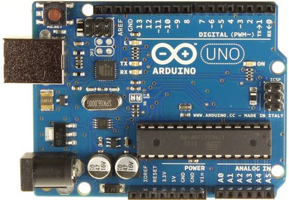
- Arduino is an open-source platform used for building electronics projects. It consists of Arduino boards and the Arduino software. Arduino board is a physical programmable circuit board, or simply called a microcontroller (MCU for microcontroller unit).
- Arduino is not a desktop computer. It is incapable of running Ubuntu Linux. It is a microcontroller that runs lower-level C-like codes.
- In the project, we will use the Arduino to act as the hardware controller. We will attach hardware components (e.g. motor) directly to the Arduino. The Arduino should receive serial communication from the Raspberry Pi to control the hardware accordingly.
I read that the Raspberry Pi is also capable of controlling hardware via GPIO. Why do we need to separate the hardware interface onto the Arduino, thus using two separate boards instead of one?
The project is designed to give an accurate representation of the development environment of the real contest robot that the current team members use.
In particular, the Raspberry Pi is designed to depict the Skull Canyon NUC on the real robot. The Arduino is designed to depict various electronic boards/drivers/PCB mounted on the robot and connected to the PC.
We hope that giving trainees experience of programming in the project can enable them to pick up tasks on the real contest robot more quickly!
2. What's Inside a Robot?
The following two guides are designed to break down the components inside a robot. After reading these you should have a better idea on the internal workings of our machines.
3. Firmware (on Arduino)
In computing, firmware is a specific class of computer software that provides the low-level control for a device's specific hardware.
First, finish Try it yourself 2 inside Lab 7.2. Arduino Serial Communication.
Next, try to finish Arduino Tutorials Learning basic control under the "Electronics Team" materials.
Warning
This part is difficult for software trainees as our focus was not on Arduino in previous parts of the training.
You are strongly strongly strongly recommended to come to M2 in person and ask us if you get stuck.
4. Hardware communication (between Arduino and Raspberry Pi)
This part should be similar to Try it yourself 2 inside Lab 7.2. Arduino Serial Communication. Try to adapt the materials to control the speed of a motor instead.
Also, in this stage, you should change the python codes such that it is a ROS node and accepts messages via subscribe to change the speed of the motor.
5. Chassis logic (on Raspberry Pi)
Materials will be provided in due course. You can expect to be more math in this part.
- Kinematics
- Localization
The end product of this part should be, you can control the chassis using the PS4 controller (similar to Assignment 1 but the turtle on the screen becomes a real robot).
6. Automous driving mission
In this part, you should use various control algorithms to allow the robot to run in a predefined path.
You might find rviz or m2_fake_robot (our self-developed visualization package) useful for programming paths for the robot.
Success
If you successfully complete all of the above, you should be able to grasp the basics of programming the real robot! However, you are just at the beginning of your journey here and there are much to learn.