Basic Control
Objectives
At the end of this self-learning lab, you should be able to:
- control motor’s rotation speed using PWM
- detect the speed of motor by speed sensor
- perform a basic feedback control
5V DC Motor
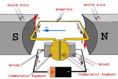
A DC motor (Direct Current motor) is the most common type of motor. DC motors normally have just two leads, one positive and one negative. If you connect these two leads directly to a battery, the motor will rotate. If you switch the leads, the motor will rotate in the opposite direction.
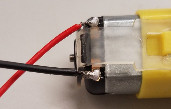
For a simple demonstration, connect the motor to the 5V pin and GND pin on Blue Bill directly. You should have soldered the wire to the motor beforehand. The motor is directly drawing current from your PC, so please try it for a few seconds only.
Code is not required for the motor to run. The 5V pin will output the voltage continuously without any code. You can reverse the two wires connected to the motor so the motor will turn in another direction.
Try it yourself 01
Fail attempt
Plug in the wires of the motor to GPIOs on Arduino, and try to control it using digitalWrite(). Why doesn't it work?
L298N Motor Driver Module
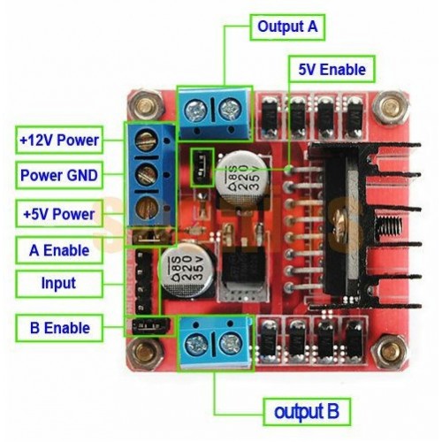
L298N is a dual full bridge driver designed to accept digital signals and drive inductive loads like DC motors. Here is a popular L298N module that can drive up to 2 motors.
Check the instructions to see how it works.
- L298N Dual H-Bridge Motor Driver User Guide
- Control DC and Stepper Motors With L298N Dual Motor Controller Modules and Arduino: 3 Steps - Instructables
Note that if you are using an external power supply, there should be a common ground connecting the power supply, L298N drive and Blue Pill.
Section Check Box:
- How to provide power to L298N driver Module
- How to connect the motors to L298N driver Module
Try it yourself 02
Need for Speed
- Instead of digital signal, applied the L298N driver with PWM signal. Try to control the speed of the motor.
- Check the supplied voltage to the DC motor using a multimeter. You may notice that the motor doesn't rotate under a certain voltage level. Find out the voltage needed to turn on the motor. Why doesn't it move?
Speed Sensor
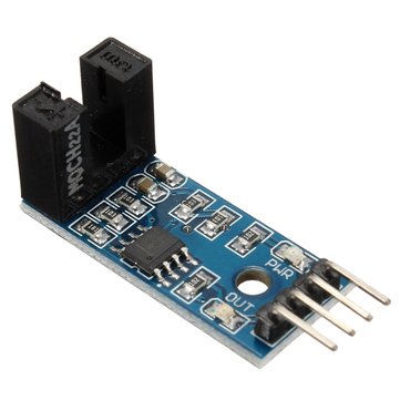
Speed sensors are used to detect the speed of a device moving or rotating. There are many kinds of speed sensors. In this lab, we will use LM393, which is a simple photo-resistor light sensor that has both analog and digital outputs. The digital output has a trim potentiometer that can be used to set a trigger light level.
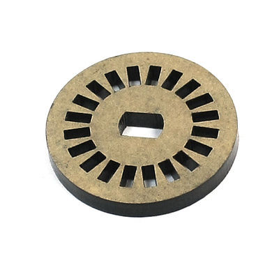
You will also need to use the encoder disc above, placing inside the gap of the speed sensor. Thus, when the disk rotates, the speed sensor can detect the rotation.
Try it yourself 03
Motor speed sensing
- Connect the encoder disc and speed sensor to the motor, and connect the digital pin of speed sensor to Blue Pill. Use digitalRead() and rotate the motor manually to observe how it behaves.
- Drive the motor with the board and write a code to measure the Revolutions Per Minute (RPM) of the motor. You may use interrupt to count the number of or with the help of built-in function pulseIn().
Feedback control
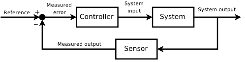
In order to control the speed of the motor, you can:
- Apply a certain voltage to the motor.
- Measure the speed of the motor and calculate the error, i.e. the difference between the desired speed and the actual speed.
- Increase the supplied voltage if the speed is too low, vice versa. It may be more responsive if the adjustment is proportional to the error.
- Repeat 2 - 3.
This is called a negative feedback control. (The same as the one you learnt in secondary school biology) This method we have used is called proportional control.
Try it yourself 04
I have complete control
- Write a code that can control the motor to rotate at around 100 RPM.
- Apply some resistance over the motor. How does the supplied voltage level changed? Can it maintain at 100 RPM?
PID controller
Proportional control is a primitive control method and has many problems:
- Slow response time
- Unable to reach target
- Overshoot and oscillate
There is another control method called PID control. It takes account of the proportional, integral, and derivative terms of the error. Our measurement here is slow and inaccurate, so PID control doesn't perform well here. However, it's better to learn more about this:
- PID controller - Wikipedia
- Improving the Beginner’s PID – Introduction - Project Blog
- PIDLibrary - Arduino Playground
Assignment 02
You accidentally made a servo motor
Write a code that can control motor speed. It should:
- Read desired speed from serial input (continuously) and rotate the motor at the desired speed.
- Print the value of currently supplied voltage and RPM of the motor.