Lab 1.4. BLDC motor and CAN communication
Estimated time to complete this lab: 2 hours
Objectives
At the end of this self-learning lab, you should be able to:
- know what is brushless DC motor
- understand the usage of CAN bus
- control brushless DC motor via CAN bus and ESC
Brushless DC motor
Reference
At the time of writing (2021), Brushless DC motor (BLDC motor) is the most common type of motor used in our team.
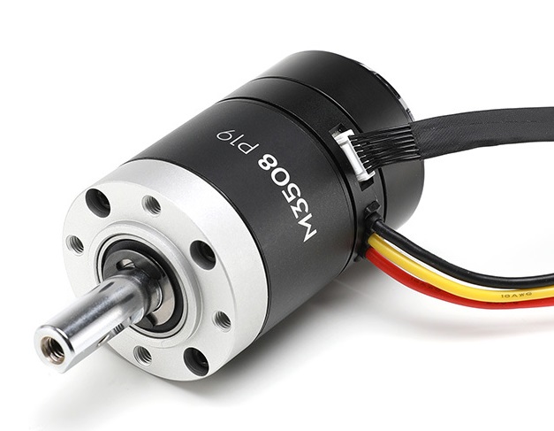
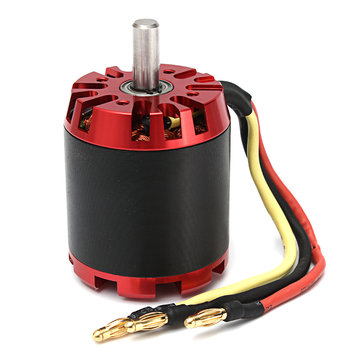
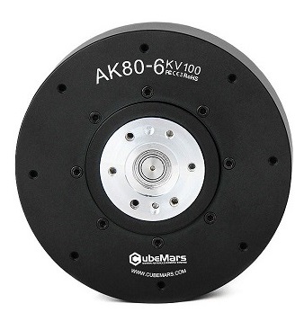
| DJI M3508 | N5065 | Tmotor AK80 |
|---|---|---|
 |
 |
 |
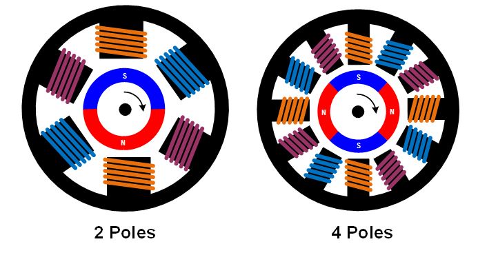
As their name implies, brushless DC motors do not use brushes. With brushed motors, the brushes deliver current through the commutator into the coils on the rotor. So how does a brushless motor pass current to the rotor coils? It doesn’t—because the coils are not located on the rotor. Instead, the rotor is a permanent magnet; the coils do not rotate, but are instead fixed in place on the stator. Because the coils do not move, there is no need for brushes and a commutator.
With the brushed motor, rotation is achieved by controlling the magnetic fields generated by the coils on the rotor, while the magnetic field generated by the stationary magnets remains fixed. To change the rotation speed, you change the voltage for the coils. With a BLDC motor, it is the permanent magnet that rotates; rotation is achieved by changing the direction of the magnetic fields generated by the surrounding stationary coils. To control the rotation, you adjust the magnitude and direction of the current into these coils.
Since the rotor is a permanent magnet, it needs no current, eliminating the need for brushes and commutator. Current to the fixed coils is controlled from the outside.
The number of windings used in a brushless motor is called the number of phases. Though brushless motors can be constructed with different numbers of phases, three phase brushless motors are the most common. With three phases, motors can be constructed with different magnetic configurations, called poles. Higher pole counts can provide higher performance, though very high speeds are better accomplished with lower pole counts.
When looking for BLDC motors, usually you will see three wires extending from the motor. These three wires correspond to the three phases in the motor (you can refer to the motors shown at the top of this lab).
Brushed DC motor
You may have heard of Brushed DC motor before in your physics class or other projects.
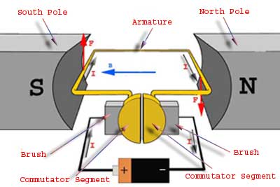
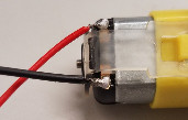
Brushed DC motors normally have just two leads, one positive and one negative. If you connect these two leads directly to a battery, the motor will rotate. If you switch the leads, the motor will rotate in the opposite direction.
To control these types of motors, one can use an H-bridge (e.g. L298N, user guide, tutorial) to control the speed and direction of the motor via digital and PWM signals.
Brushed motors are easier to control than Brushless motors. However, brushless motors provide longer lifetime, higher speed and acceleration and higher efficiency compared to brushed motors, so we usually use brushless motors on our robot.
BLDC Controller
The control of the individual three phases of a BLDC motor is quite complicated and advanced. What most people do to control a BLDC is use a separate circuit/board called Electronic Speed Controller (ESC). The ESC receives the motor target control (e.g. position, velocity, current) signals, then controls the motor by activating the appropriate MOSFETs to create the rotating magnetic field so that the motor rotates.
At the training level, it is not needed to understand the detailed control of the phases of the BLDC. From the programmer's perspective, the main focus should be on (1) how to communicate with the ESC, and (2) what signals to pass to the ESC. How to control the phases in a BLDC is an industrial-level topic. In fact, some more expensive motors have their own dedicated ESC to go along with them (built into the motor itself), and they have their own ways to control the phases.
The ESC has several IO that you should care about:
- Input power supply, usually two wires (positive and negative)
- Input control signal (e.g. CAN bus, will be discussed in following section)
- Input motor sensor feedback (e.g. motor rotor position, motor velocity, ...)
- Output three phase for BLDC
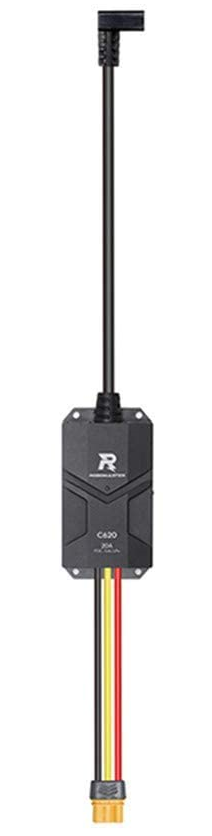
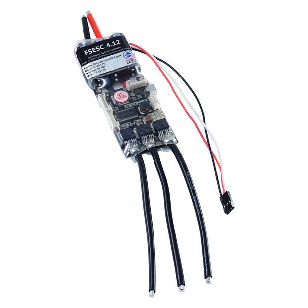
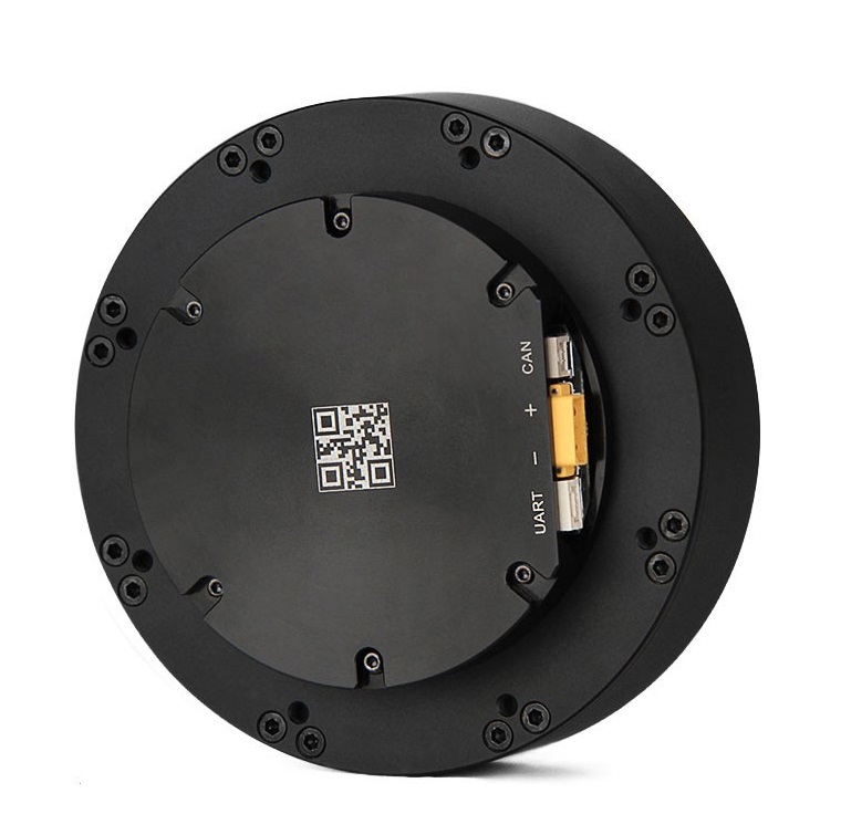
Below shown are several ESC commonly used in M2. Can you guess which wires/ports correspond to which functionality?
| DJI C620 | VESC 4.12 | Tmotor AK80 (inbuilt ESC) |
|---|---|---|
 |
 |
 |
Section Check Box:
- What is a BLDC motor
- Relationship between BLDC motor and ESC
CAN
A Controller Area Network (CAN bus) is a robust vehicle bus standard designed to allow microcontrollers and devices to communicate with each other's applications without a host computer. It is a message-based protocol, designed originally for multiplex electrical wiring within automobiles to save on copper, but it can also be used in many other contexts.
CAN was invented by Bosch, in Germany, in 1983 and first used in the Mercedes-Benz W140 in 1991. Modern cars may have around seventy electronic devices: sensors and actuators, an engine management unit and an automated engine start/stop system. These rely on getting readings from sensors such as accelerometers, thermometers and gas sensors, and sending commands to actuators. Obviously, great accuracy is required and the CAN bus has a great deal of cyclic redundancy checking (CRC) built in to ensure safety. The system is robust towards electric disturbances and electromagnetic interference - ideal for safety critical applications (e.g. vehicles)
Although originally designed for use in automotive situations this bus offers a simple and inexpensive system for use in hobby electronics projects. CAN is also frequently used in M2 for communication between different MCU and computers.
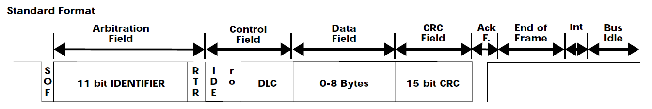
The fields of a standard CAN frame
Reference
- 成大資工 Wiki - CAN: http://wiki.csie.ncku.edu.tw/embedded/CAN (mainly 1.DATA FRAME(資料通訊格式))
- https://www.ccontrols.com/pdf/CANtutorial.pdf
A CAN frame consists mainly of an identifier field, a control field and a data field. The control field is six bits long, the data field is zero to eight bytes long and the identifier field is 11 bits long for standard frames, or 29 bits long for extended frames.
Identifier field
CAN transmissions operate using the producer/consumer model. When data are transmitted by a CAN device, no other devices are addressed. Instead, the content of the message is designated by an identifier field. This identifier field, which must be unique within the network, not only provides content but the priority of the message as well. All other CAN devices listen to the sender and accept only those messages of interest. This filtering of the data is accomplished using an acceptance filter which is an integral component of the CAN controller chip. Data which fail the acceptance criteria are rejected. Therefore, receiving devices consume only that data of interest from the producer.
Small data frames are used with a maximum of 8 bytes of data in each data packet. Each node has an ID number and transmission clashes on the network are dealt with by the lower priority frame backing off. Priority depends on the allocated ID given to the device. Lower ID numbers have higher priority.
Control field
- DLC is used to specify the data length (number of bytes) in the data field.
- IDE is used to specify the CAN standard (Standard vs Extended)
- R0 is reserve
Data field
- Stores the user data to be sent over the bus, can be 0-8 bytes long.
It is important to understand how to use the CAN interface in order to communicate with the ESC and other MCU used on the robot. Usually the documentation of the ESC will provide some information on how the programmer should package the CAN message to send certain commands.
Example: DJI C620
Source / Official user guide: https://rm-static.djicdn.com/tem/17348/RoboMaster%20C620%20Brushless%20DC%20Motor%20Speed%20Controller%20V1.01.pdf
Section Check Box:
- What is CAN bus, advantages of using CAN bus
- Important fields in a CAN frame
Implementation
Let's use an Arduino to read and write from the C620+M3508.
Things you need
- MCP2515 CAN Controller module
- M3508 motor
- C620 controller
- Suitable wires
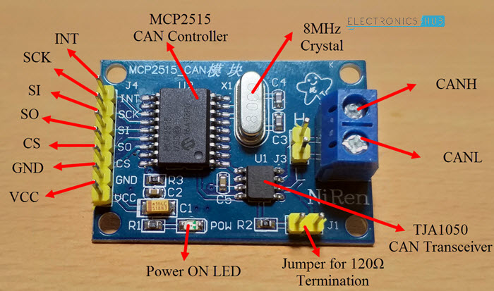
The more you know: MCP2515 CAN Controller module
The MCP2515 CAN Controller module has two components: MCP2515 CAN Controller IC and TJA1050 CAN Transceiver IC:
- MCP2515 CAN Controller: Due to hardware limitations, Arduino alone does not support CAN. However, it does support SPI. The MCP2515 IC is a standalone CAN Controller and has integrated SPI Interface for communication with microcontrollers.
- TJA1050 CAN Transceiver: A CAN transceiver is the interface between the controller and the CAN bus. The transceiver translates the logic level messages from the controller into the CAN differential scheme on the CANH and CANL pins of the CAN transceiver. The controller can be thought of as an MCU, the part of the CAN node that processes all the information to and from the CAN bus.
- The two IC combined form the whole module. You can treat it as an "SPI to CAN converter".
Wiring
Please wire the components as follows:
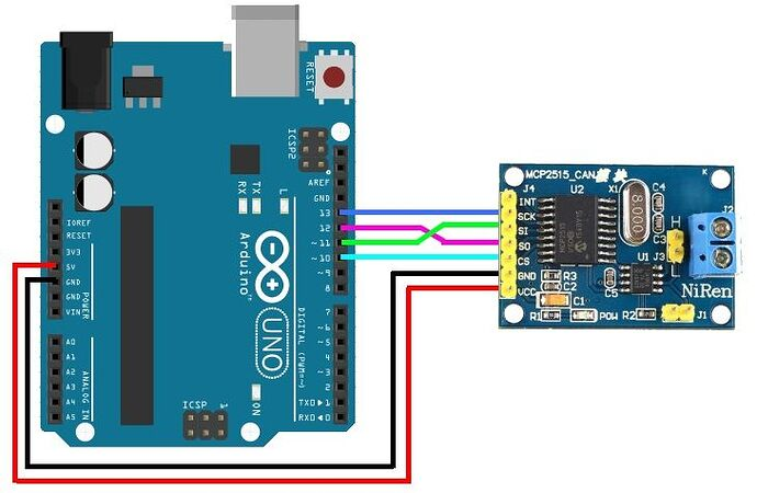
Step 1: Connect MCP2515 CAN module with Arduino Uno with dupont lines. Connect the pins from MCP2515 CAN module to corresponding pins on the Arduino Uno. You can also refer to the website here
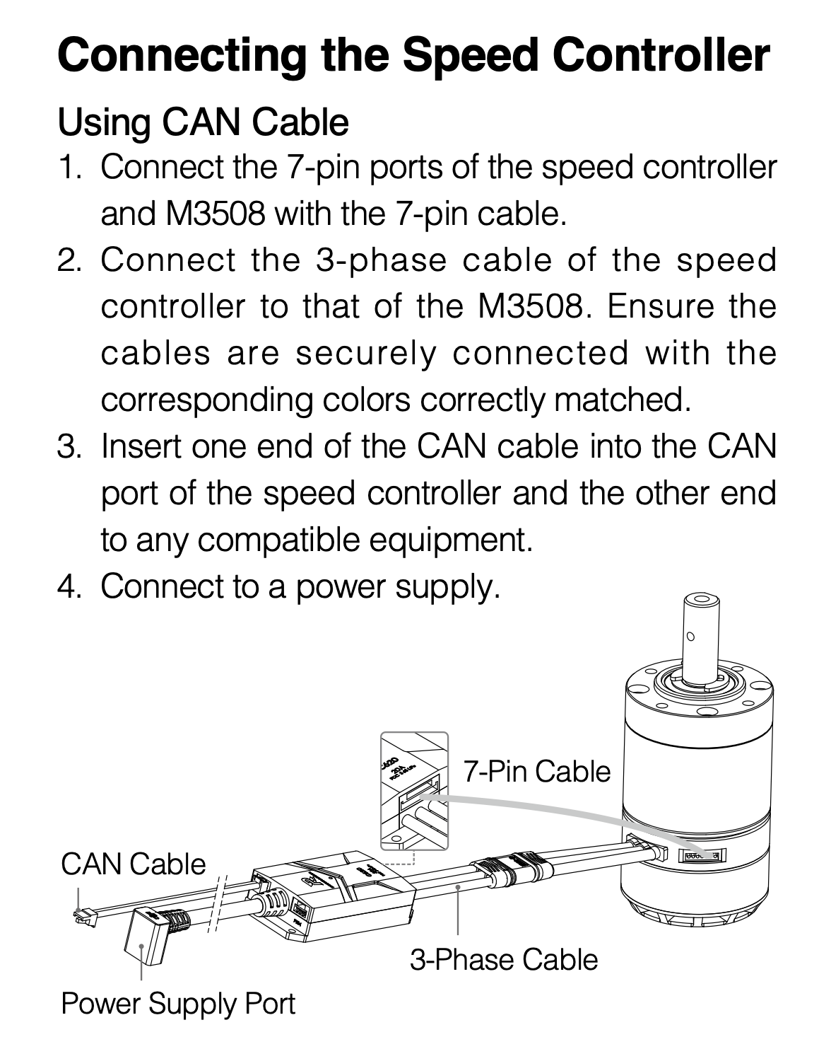
Step 2: Connect M3508 motor to the C620 speed controller. Please refer to the figure below. Source: C620 datasheet
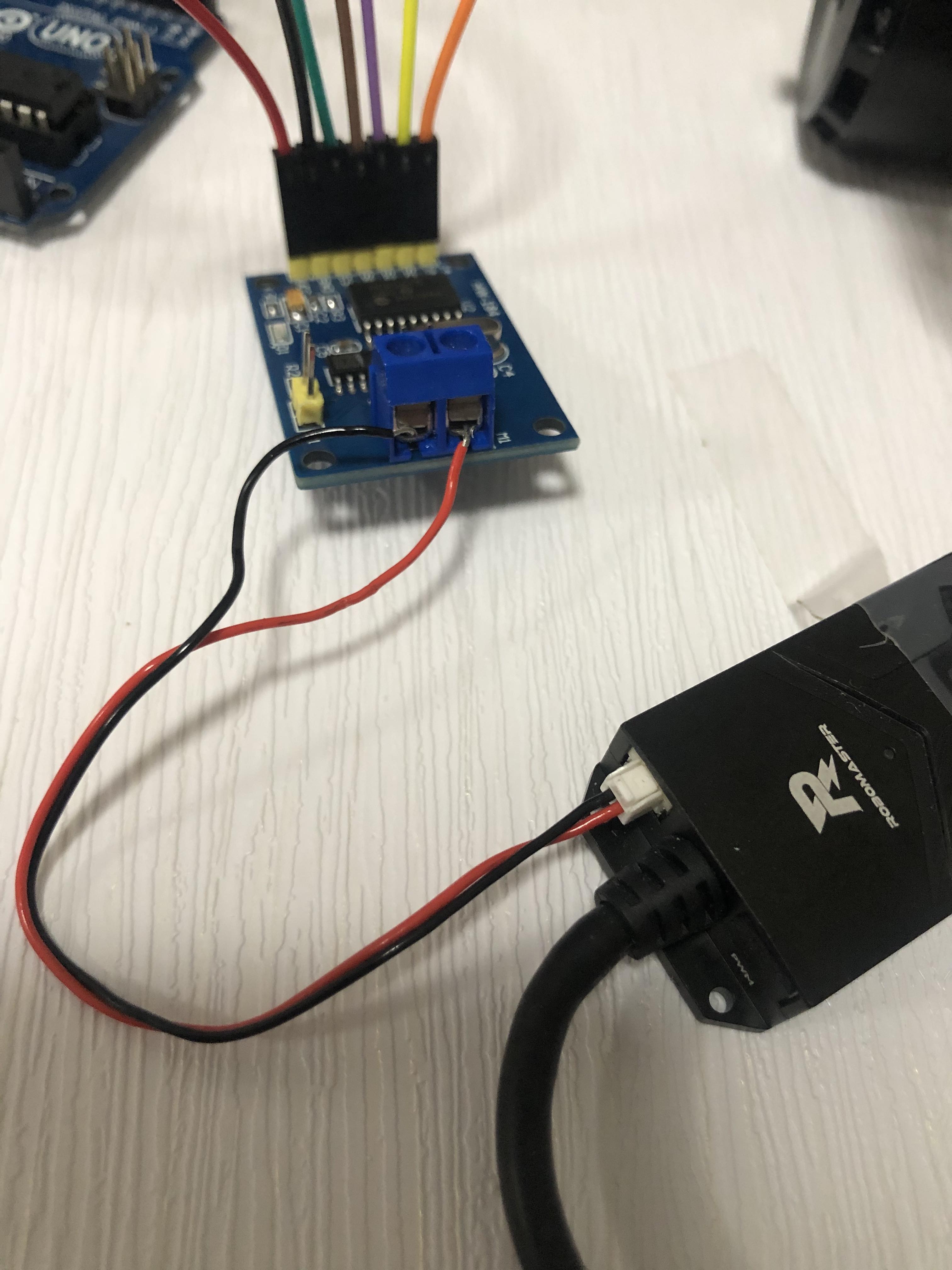
Step 3: Connect the red wire and black wire of CAN cable on the C620 to CANH and CANL on the MCP2515 CAN module respectively. Source: here
Step 4: Connect power supply port of the C620 to a power supply using appropriate connectors and wires.
Step 5: Below are pictures of the whole setup. Please check the connections carefully before moving forward.
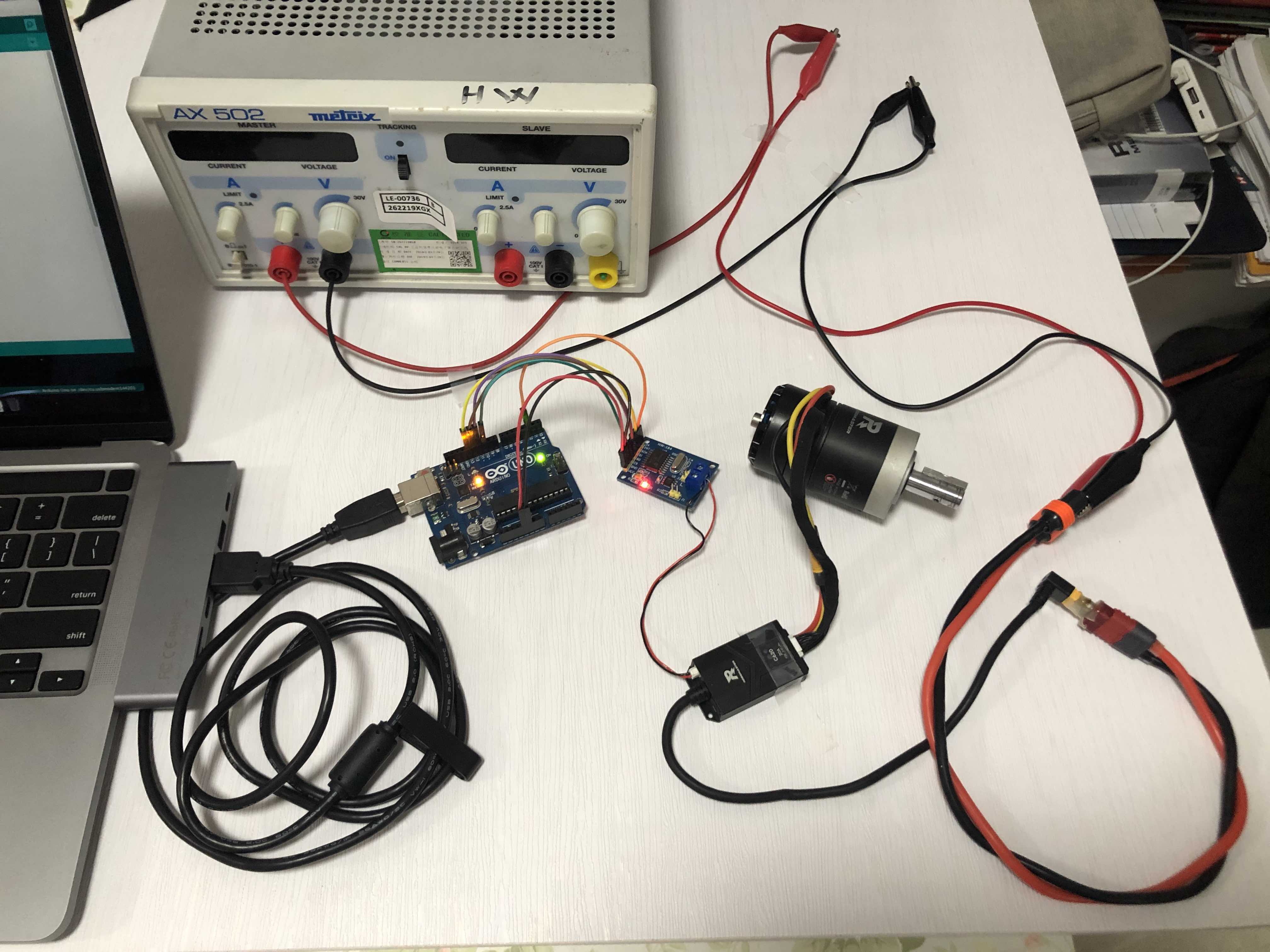
Danger
You MUST notify our team members and let them check your connection circuit before turning on the power supply and proceeding with this lab. Otherwise, if there are mistakes in your wiring (e.g. short circuit, inverting positive and negative), accidents such as fire and explosion may occur and you may be injured.
Turn on the power supply. Adjust the voltage and current such that it shows "24V, 0.5A".
If the power connection is fine, you should see that a green light is flashing on the C620 controller, and some buzzing sound is emitted from the M3508 motor.
You might have to restart the power supply (perform power cycle) after adjusting the voltage and current.
Library installation
We need a library to use the MCP2515 with Arduino.
Similar to the sensor library installation in the previous section, we should git clone the library into the lib directory.
You can use this library: https://github.com/autowp/arduino-mcp2515
$ cd lib
$ git clone https://github.com/autowp/arduino-mcp2515.git
Have a look at the example code of the library under examples.
In particular, have a look at CAN_write.ino and CAN_read.ino.
You should note what important fields/functions there are and how to use them, such as setBitrate(), can_id, can_dlc, data, sendMessage().
Read data from C620
Try to modify the example code in CAN_read.ino to read data from the C620. In particular, note that:
- the CAN bitrate should be 1MHz when communicating with the C620 (you can refer to the C620 datasheet here). You can refer to
mcp2515.hinside the library to check how to change the bitrate. - the oscillator on the MCP2515 module is 8MHz. You should specify it in
setBitrate()along with the CAN bitrate. Refer tomcp2515.hon how to do this. - the baudrate of the serial communication in the sample code is 115200 bps, but the default baudrate of the PlatformIO serial monitor is 9600 bps. You should adjust the settings in the serial montior so the speed is 115200 bps (refer to here for more details).
The more you know
Recall that bps stands for "bits per second".
Higher speed is needed because the C620 will perform 1000Hz communication with Arduino, and we are performing serial communication between Arduino and computer on every successful CAN communication. This means we will perform communication between Arduino and computer every 1000Hz.
9600 bps is not fast enough for our communication because this means we only have 9.6 bits to use for each 1000Hz !
Note that you can only communicate with the C620 when the power supply is turned on (i.e. flashing green light).
You can consider the communication successful if you can print the bytes on your serial monitor, and that the reading changes only when the motor is moved (you can try turning the back of the M3508 motor with your hand!).
Classwork 1.4.1
The bytes printed on the screen can be considered as the "raw frame data". We need to extract information from it for it to become useful.
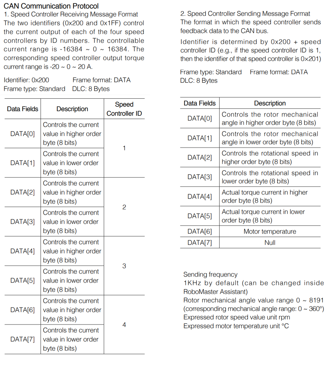
Refer to the "CAN Communication Protocol" of the C620 datasheet, and look for "2. Speed Controller Sending Message Format".
- Notice that the rotor position (the angle of the motor) is stored in the first two bytes of the data frame.
- Try to use C++ bitwise operators to extract the rotor position. You should obtain a number from 0 to 8191. Output this number to the serial monitor. When turning the rotor with your hand, the number should be increasing/decreasing and wraparound after 8191 or below 0.
- Notice that the motor velocity (rpm) is stored in the next two bytes of the data frame.
- Try to use C++ bitwise operators and cast to extract the signed rotor velocity. You need to do some special handling for the negative direction. Output the RPM to the serial monitor along with the rotor position.
- Make sure that positive number can be shown when you rotate the motor in one direction, and negative number is shown when you rotate the motor in the opposite direction.
- Knowledge on "Two's complement" might also be useful here.
Please approach our team members after you have completed the task. In your training repository, save the code into a new file named cw-1-4-1.cpp. Commit and push the code. If you don't know how to use git/github, you can refer to the internal git tutorial here.
Write data to C620
Try to modify the example code in CAN_write.ino to write data to the C620 and move the motor. In particular, note that:
- the CAN bitrate should be 1MHz when communicating with the C620 (you can refer to the C620 datasheet here). You can refer to
mcp2515.hinside the library to check how to change the bitrate. - the oscillator on the MCP2515 module is 8MHz. You should specify it in
setBitrate()along with the CAN bitrate. Refer tomcp2515.hon how to do this. - the
can_idshould either be0x200or0x1FF, please refer to the instructions below on whichcan_idto use. - there is internal timeout of the C620 and cut current if it has not received CAN message for a while. Thus, you should keep on sending CAN message to the C620 (at a high enough frequency).
Note that you can only communicate with the C620 when the power supply is turned on (i.e. flashing green light).
Warning
If everything is right (the write communication is successful), the motor will begin to move. As the motor is quite strong and can spin quite fast, you are advised to take caution.
Classwork 1.4.2
Referring to the communication protocol in the datasheet (page 14 to 17), a single CAN message can control multiple ESC with different ID (CAN bus is designed such that multiple devices can use the same bus (share the same two wires), but here we are only using one), each ESC being commanded by the respective two consecutive bytes inside the CAN frame. The two bytes refer to the motor current.
You can treat motor current as controlling the stength of the magnets in the BLDC, so it is similar to the "torque" of the motor. Because \(F = ma\), you can also treat it similar to the "acceleration" of the motor"
Try to change the bytes of the CAN frame being written. How is the behavior of the motor different after power cycle?
You are advised to store the current command value inside a short variable, then extract the high bytes and low bytes
of the variable (by again using some bitwise operators)
to place inside the appropriate fields in the CAN frame.
Try to change the value of that variable so that you can assign current commands easily. Try to assign a negative number to the variable, so that the motor rotates in the opposite direction. Does it work as intended?
You can try the following test cases:
- Assign
512to the current value, it should spin in one direction. - Assign
1024to the current value, it should spin in the same direction, but faster. - Assign
-512to the current value, it should spin in the opposite direction. - Assign
-1024to the current value, it should spin in the opposite direction, but faster.
While the motor is in motion, try to adjust the current (A) of the power supply. What happens?
Please approach our team members after you have completed the task. In your training repository, save the code into a new file named cw-1-4-2.cpp. Commit and push the code. If you don't know how to use git/github, you can refer to the internal git tutorial here.
Appropriate CAN ID and message field
In the previous section of reading data from the C620, on each successful communication, you should be able to read the CAN ID of the feedback frame.
The C620 sends a feedback CAN frame with the CAN ID equal to 0x200 + speed controller ID
(e.g. if the speed controller ID is 1, then the identifier of that speed controller is 0x201).
In the command CAN frame that the Arduino sends out, you should change the CAN ID and corresponding CAN message fields in the command frame, such that the changed value corresponds to that speed controller ID. For example:
- If the CAN ID in the feedback frame is
0x201, then the speed controller ID is 1. Thus the CAN ID in the command frame should be0x200, and you should changedata[0]anddata[1]fields inside the command CAN message. - If the CAN ID in the feedback frame is
0x206, then the speed controller ID is 6. Thus the CAN ID in the command frame should be0x1FF, and you should changedata[2]anddata[3]fields inside the command CAN message.
Appropriate value of current
In the C620 CAN protocol, the signed current value is spread across 2 bytes. The controllable current range is -16384 ~ 0 ~ 16384. The corresponding speed controller output torque current range is -20 ~ 0 ~ 20A.
As the power supply has a current output limit (we previously set it to 0.5A), we should not write values to the C620 that are greater than 0.5A.
The default values in the MCP2515 sample code have current values that are quite high (absolute value > 5A). You should adjust the value of the bytes such that the current value is no greater than 1A.
However, the current value should also not be too small. The current value should also be great enough to overcome the static friction of the motor. If the current value is too small, you may need to give the motor a slight push to overcome the static friction before it starts turning.
Section Check Box:
- Read data from C620
- Write data to C620