Servo and Sensors
Objectives
At the end of this self-learning lab, you should be able to:
- control servo motors
- read analog signal
- understand analog signal reading and I2C communication protocol
- take reading from different sensors
Servo motor
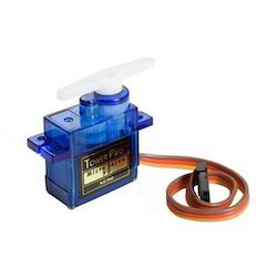
A servo motor is a rotary actuator or linear actuator that allows for precise control of angular or linear position, velocity and acceleration. Because servo motors use feedback to determine the position of the shaft, you can control that position very precisely. As a result, servo motors are used to control the position of objects, rotate objects, move legs, arms or hands of robots, move sensors etc. with high precision.
Read more about servo motor from the following websites.
- Servomotor - Wikipedia
- How Servo Motors Work | Servo Motor Controllers
- Arduino : How to Control Servo Motor With Arduino - Instrutables
You should notice that you need to use a library when you want to turn the servo motor to a designated position. The description of the library is as follows.
Yet, the angle of servo motor is just controlled by PWM, which we have learnt before. Thus, we can also write a code to make a servo motor turn without using a library. Here is an example.
Try it yourself 01
Servo Motor Controlling
- Write a code which turns exactly 45 degrees and stops there.
- Write a code which controls the servo motor to rotate back and forth.
Analog Signal
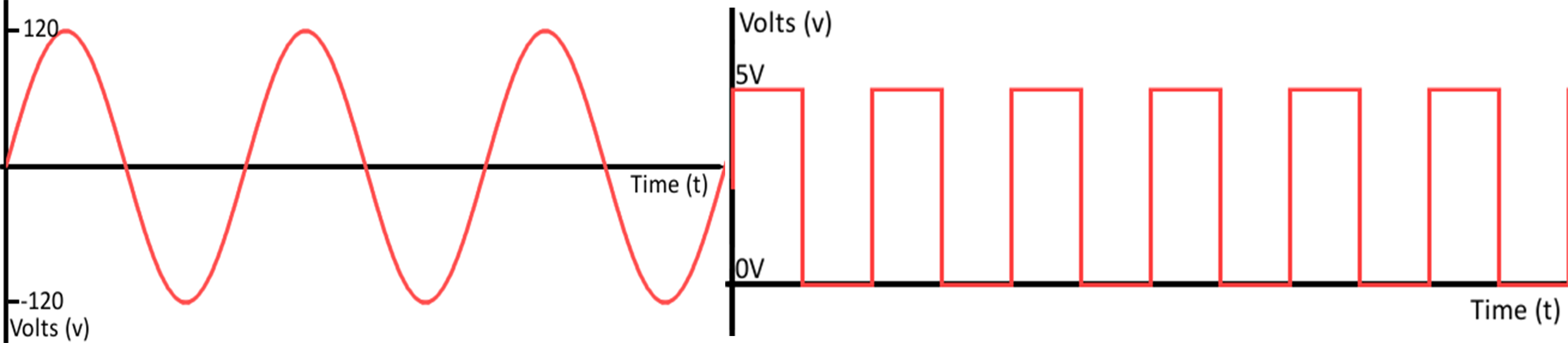
Analog signal is sent and received in the form of a wave. Digital signal is the opposite of analog signal. For the graph above, the L.H.S. expresses what an analog signal looks like, while the one on the right imitates a digital signal. You can imagine there is a door, digital signal can only tell you whether the door is closed or opened, but analog signal can tell you how wide is the door opening.
Receiving and sending analog signals in Arduino is as easy as tackling digital signals. Read the following sites to learn more about analog signals.
- Analog vs Digital
- Analog input in Arduino
- IR distance sensor measurement
- Build a distance sensor from scratch
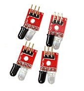
This is an IR distance sensor, which radiates IR light and measures the amount of IR reflected. It output analog singal with can be read by Blue Pill through any pin that support ADC. Let's connect the sensor to Blue Pill.
- VCC: 5V
- GND: you guese it
- A0: pin that support ADC
const int SENSOR_PIN = PA0;   // or any other pin you like

void setup() {
  delay(1500);
  Serial.begin(9600);
  pinMode(SENSOR_PIN, INPUT); // pinMode can also be set as INPUT_ANALOG, but then it won't be able to use digitalRead() on the same pin
}

void loop() {
  Serial.println(analogRead(SENSOR_PIN));
  delay(1000);
}
Try it yourself 03
Planet Analogue and Planet Di Gi Charat
The signal can also be treated as a digital signal. Use digitalRead() and analogRead() at the same time and determine the threshold voltage that differentiate a HIGH signal from a LOW signal.
I²C communication protocol
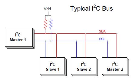
I²C is a communication protocol which allows master devices to send and receive data from slave devices. Although the speed of data transmission through I²C is not very fast (~100kbits/s), it occupies a very little number of connections to establish a connection between devices. Moreover, the number of connections needed does not increase with an increase in devices. This makes I²C a very popular protocol in MCU-sensor connections.
Find out more about I²C from the following websites.
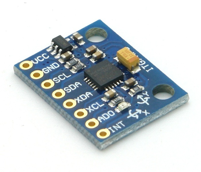
MPU6050 is an IC with a 3-axis gyroscope, a 3-axis accelerometer and temperature sensor. It uses I²C to communicate. Here is an example code to use MPU6050:
// MPU-6050 Short Example Sketch
// By Arduino User JohnChi
// August 17, 2014
// Public Domain
#include <Wire.h>

const int MPU_ADDR = 0x68;                 // I2C address of the MPU-6050
void setup()
{
    Wire.begin();
    Wire.beginTransmission(MPU_ADDR);
    Wire.write(0x6B);                      // PWR_MGMT_1 register
    Wire.write(0);                         // set to zero (wakes up the MPU-6050)
    Wire.endTransmission(true);
    Serial.begin(9600);
}
void loop()
{
    int16_t ac_x, ac_y, ac_z, temp, gy_x, gy_y, gy_z;

    Wire.beginTransmission(MPU_ADDR);
    Wire.write(0x3B);                      // starting with register 0x3B (ac_CEL_XOUT_H)
    Wire.endTransmission(false);
    Wire.requestFrom(MPU_ADDR, 14);        // request a total of 14 registers
    ac_x = Wire.read() << 8 | Wire.read(); // 0x3B (ac_CEL_XOUT_H) & 0x3C (ac_CEL_XOUT_L)
    ac_y = Wire.read() << 8 | Wire.read(); // 0x3D (ac_CEL_YOUT_H) & 0x3E (ac_CEL_YOUT_L)
    ac_z = Wire.read() << 8 | Wire.read(); // 0x3F (ac_CEL_ZOUT_H) & 0x40 (ac_CEL_ZOUT_L)
    temp = Wire.read() << 8 | Wire.read(); // 0x41 (TEMP_OUT_H) & 0x42 (TEMP_OUT_L)
    gy_x = Wire.read() << 8 | Wire.read(); // 0x43 (gy_RO_XOUT_H) & 0x44 (gy_RO_XOUT_L)
    gy_y = Wire.read() << 8 | Wire.read(); // 0x45 (gy_RO_YOUT_H) & 0x46 (gy_RO_YOUT_L)
    gy_z = Wire.read() << 8 | Wire.read(); // 0x47 (gy_RO_ZOUT_H) & 0x48 (gy_RO_ZOUT_L)
    Serial.print("Temp = ");
    Serial.print(temp / 340.00 + 36.53);   // equation for temperature in degrees C from datasheet
    Serial.print("\tAcc X = ");
    Serial.print(ac_x);
    Serial.print(" Y = ");
    Serial.print(ac_y);
    Serial.print(" Z = ");
    Serial.print(ac_z);
    Serial.print("\tGyro X = ");
    Serial.print(gy_x);
    Serial.print(" Y = ");
    Serial.print(gy_y);
    Serial.print(" Z = ");
    Serial.println(gy_z);
    delay(333);
}
Further Readings
Try it yourself 03
MPU6050 Gyroscope
- Try to detect whether the MPU6050 breakout board is tilted using the gyroscope and/or the accelerometer readings.
Library
What is library? It is code that written and contributed by many different people. It provides many great additional capabilities to run new and different hardware devices. The code will be inserted in your code if you add a library to your code. Find out more by yourself.
It is possible to calculate odometry using either gyroscope or the accelerometer readings. However, accelerometer is noisy and hence is inaccurate in short term; while gyroscope drifts and hence is inaccurate over long term. Here comes Kalman Filter to save the world. It fuses different measurements over time to provide a better estimation of the value. It is a difficult topic in robotics, so understanding and using of Kalman filter is not required at this stage. Just for your reference.
Understanding how the stuff works is a bit complicated for beginners. Thus, there are always geniuses which make a library by themselves. We can include the library so that values can be obtained by just calling the corresponding function. There is a Arduino library for Kalman Filer:
Try it yourself 04
kalman Filter
Install a Kalman filter library to the project and use it to filter the output of MPU6050
Assignment 03
clickclickclick
There was a game called clickclickclick.com, which players compete to make most mouse clicks in a week. People use different methods to fight for their victory. Unfortunately, it was closed in 2017, but we can still make a robot that click your mouse automatically to memorize this game.
- Use a servo to click a mouse automatically.
- As the user may want to temporarily use the mouse and move the mouse away, it should stop clicking when the mouse isn't nearby. Use a IR distance sensor to detect the presence of the mouse. You may want to use a mouse that's white in colour.
- It is dangerous if the robot still operate when it's falling! Stop servo action when it suspects that it is falling and restart only when there's a user reset.
References
- SG90 Digital - Tower Pro
- MPU-6050 - Arduino Playground
- MPU6050 breakout board GY-521 Datasheet
- MPU6050 Datasheet