Lab 1.3. Incremental encoder and library
Estimated time to complete this lab: 1 hour
Objectives
At the end of this self-learning lab, you should be able to:
- understand what is incremental encoder and its working principle
- install libraries
Incremental encoder
Reference: https://en.wikipedia.org/wiki/Incremental_encoder
An incremental encoder is a linear or rotary electromechanical device that has two output signals, A and B, which issue pulses when the device is moved. Together, the A and B signals indicate both the occurrence of and direction of movement.
An incremental encoder employs a quadrature encoder to generate its A and B output signals. The pulses emitted from the A and B outputs are quadrature-encoded, meaning that when the incremental encoder is moving at a constant velocity, the A and B waveforms are square waves and there is a 90 degree phase difference between A and B.
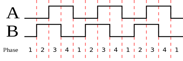
By counting the pulses and tracking the AB phases, we are able to obtain the relative rotation from the initial orientation of the encoder.
The unit is "counts". It can be any integer (positive, zero, negative). We will be able to know how many counts the encoder has rotated relative to some initial state (e.g. from beginning of program and power on).
Unlike an absolute encoder, an incremental encoder does not indicate absolute position; it only reports changes in position and, for each reported position change, the direction of movement.
The frequency of the pulses on the A or B output is directly proportional to the encoder's velocity (rate of position change); higher frequencies indicate rapid movement, whereas lower frequencies indicate slower speeds. Static, unchanging signals are output on A and B when the encoder is motionless.
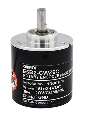
E6B2-CWZ6C
E6B2-CWZ6C is an incremental ABI encoder. In our project, we will use the model with 1024 pulses/rotation (please ignore the resolution in the label in the diagram below).
If you are interested, you can read its datasheet here: https://www.ia.omron.com/data_pdf/cat/e6b2-c_ds_e_6_1_csm491.pdf
From the datasheet, there are some useful details, the most important being the resolution (1024 pulses/rotation) and power supply voltage (5V to 24V DC). It is important that the encoder works at 5V (but not requiring higher voltage), because the Arduino can only give out 5V when powered via USB.
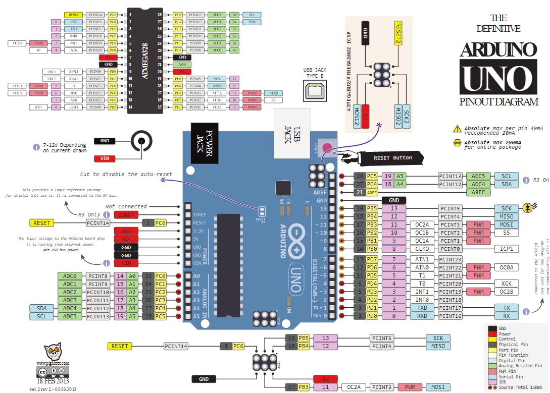
Encoder wiring
Please make the following connections by yourself (you may use the breadboard if needed):
| Pin on AS5600 | Pin on Arduino |
|---|---|
| VCC (Brown) | 5V |
| GND (Blue) | GND |
| Out A (Black) | 2 |
| Out B (White) | 3 |
To understand the above table, may refer to the information on the label stuck on the encoder, and Arduino UNO pinout.
Reading encoder data via polling
Now, try the following code:
#include <Arduino.h>

int prev_a, prev_b;

void setup(){
    pinMode(2, INPUT_PULLUP); // configure pin 2 as input pin
    pinMode(3, INPUT_PULLUP); // configure pin 3 as input pin
    Serial.begin(9600);
    prev_a = digitalRead(2);
    prev_b = digitalRead(3);
}

void loop() {
  int new_a = digitalRead(2);
  int new_b = digitalRead(3);
  if (new_a != prev_a || new_b != prev_b) {
    Serial.print(new_a);
    Serial.print(new_b);
    Serial.print('\n');
  }
  prev_a = new_a;
  prev_b = new_b;
}
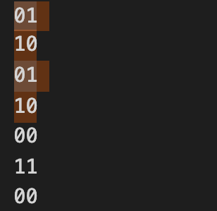
Now, rotate the shaft of the incremental encoder slowly. You should note that the phases of the encoder reading change as you rotate the shaft.
In particular, the pattern of the phases should follow the pattern shown in the diagrams in the previous section (00, 01, 11, 10, ...).
What happens when you rotate the shaft in the opposite direction?
Classwork 1.3.1
Wire the encoder to the Arduino following the table shown above.
Write a piece of code to output the signed count of the encoder relative to the power-on state. You should use digitalRead(...) to read the sensor data. You should output the value to the serial monitor.
You probably need to consider the values in the current loop iteration, and compare them to those in the previous loop iteration.
In particular,
- When the MCU is first turned on, it should output the value
0. - When the shaft is rotated 90 degrees clockwise (relative to the power-on state), it should output
1024(because it is a quadrature encoder, the actual phase is multiplied by 4). - When the shaft is rotated 360 degrees clockwise (relative to the power-on state), it should output
4096. - When the shaft is rotated 720 degrees clockwise (relative to the power-on state), it should output
8192. - When the shaft is rotated 90 degrees anticlockwise (relative to the power-on state), it should output
-1024. - So on...
Please approach our team members after you have completed the task. In your training repository, save the code into a new file named cw-1-3-1.cpp. Commit and push the code. If you don't know how to use git/github, you can refer to the internal git tutorial here.
Interrupt
Now, rotate the shaft of the incremental encoder quickly. You should note that the phases of the encoder reading change as you rotate the shaft. Does the pattern of the phases still maintain the correct cyclic pattern?
You should notice that the pattern of the phases cannot maintain the correct cyclic pattern when the shaft is turned quickly. This is because in the above code, we use the polling method to read the encoder data.
In polling, the CPU keeps on asking the device for the sensor reading, inside the loop. The CPU steadily ballots the device at a regular interval. Polling is slow because the processor waste countless processor cycles by repeatedly checking the status of each device.
A better method to use is interrupt. Interrupts are useful for making things happen automatically in microcontroller programs and can help solve timing problems. Good tasks for using an interrupt may include reading a rotary encoder, or monitoring user input.
If you wanted to ensure that a program always caught the pulses from a rotary encoder, so that it never misses a pulse, it would make it very tricky to write a program to do anything else, because the program would need to constantly poll the sensor lines for the encoder, in order to catch pulses when they occurred. Other sensors have a similar interface dynamic too, such as trying to read a sound sensor that is trying to catch a click, or an infrared slot sensor (photo-interrupter) trying to catch a coin drop. In all of these situations, using an interrupt can free the microcontroller to get some other work done while not missing the input.
Simply put, you can make the microprocessor automatically call an ISR (Interrupt Service Routines) based on different trigger conditions based on the digital input, such as LOW, CHANGE, RISING, and FALLING.
However, interrupts are more difficult to implement and get right. You can see here for more information.
Library
If we are using hardware that is somewhat popular (e.g. incremental encoder, Arduino), chances are that someone else in the world has already written the communication and data processing part as a library, and we can simply use their code without having to reinvent the wheel. Simply put, we can "borrow" someone else's code to read the sensor reading and data processing of incremental encoder in our Arduino board.
Here, the Encoder library can help us to do the interrupt implementation of reading encoder data properly.
What is a library?
A library is code that written and contributed by many different people. It provides many great additional capabilities to run new and different hardware devices. The code will be inserted in your code if you add a library to your code.
The first step to installing a library, obviously is to look for the library!
You can use the following library: https://github.com/PaulStoffregen/Encoder
To install the library:
- Clone/download the entire git repository and place it in the
libfolder.
$ cd lib
$ git clone https://github.com/PaulStoffregen/Encoder.git
- You can open the example code to see how to use the library. Usually, look for a folder named
examplesand look for the example usage of the library.
In this case, you will find lib/Encoder/examples/Basic/Basic.pde (online) worth looking at.
Classwork 1.3.2
Wire the encoder to the Arduino following the table shown above.
Copy the code from Basic.pde into src/main.cpp.
At the beginning of the code, you should change the pins to (2, 3) as those pins support interrupt on Arduino UNO.
Try to upload the example code into the Arduino, then rotate the incremental encoder while the serial monitor is open.
You should see the sensor reading change when you rotate the shaft of the incremental encoder.
Please approach our team members after you have completed the task. In your training repository, save the code into a new file named cw-1-3-2.cpp. Commit and push the code. If you don't know how to use git/github, you can refer to the internal git tutorial here.
Section Check Box:
- Working principle of incremental encoder
- Using incremental encoder
- What is a library
- How to install and include library
- How to use Encoder library