Supplementary: Timer, PWM and Interrupt
Objectives
At the end of this self-learning lab, you should be able to:
- Use External Interrupt
- Use Timer Interrupt
Info
This lab is optional. It lets you learn more intermediate but useful programming techniques in Arduino. If you find it difficult, feel free to skip this lab.
Things you need
- Solderless breadboard
- LED
- A resistor, anything between a few hundred to a few thousand ohms is OK. Check the resistance with a multimeter or by reading the color code on it.
- Momentary button
- Hookup wire (or Dubon wires as we like to call them)
External Interrupt
You may have heard of interrupt service routine (ISR), which is a piece of code triggered by a interrupt signal.

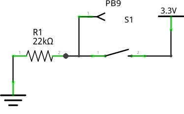
On Arduino Uno, one pin 2 and pin 3 support interrupt. Connect a button to pin 2 like this.
Run the following code:
const int BTN_PIN = 2;

bool g_state = false;

void handler(void);

void setup() {
  pinMode(LED_BUILTIN, OUTPUT);
  pinMode(BTN_PIN, INPUT_PULLDOWN);

  attachInterrupt(BTN_PIN, handler, RISING);
}

void loop() {
}

void handler(){
  g_state = !g_state;
  digitalWrite(LED_BUILTIN, g_state);
}
Here handler() is called once the button is pressed.
Further Reading
Try it yourself
Control a breathing light
Make a breathing light that turns on only when the button is pressed. Make use of external interrupt.
Timer Interrupt
Arduino has hardware timers, each consist of a counter and several registers to control the behaviour of the counter. The counter increments from 0 to its maximum, and then back to 0 again. (In upcounting mode. There are also downcounting mode, which behave similarly)
It is possible to generate interrupt signals using a timer. The function can be executed at a regular time intervals. This is especially useful in real-time control.
Here we will be using the PC13 LED as an example:
const int LED_PIN = LED_BUILTIN;
const int LED_RATE = 500000;  // in microseconds; therefore the interrupt handler will be called every 0.5s

void handler_led(void);

int g_state = 0;

void setup()
{
  pinMode(LED_PIN, OUTPUT);

  // Setup LED Timer
  // In output compare mode, timer counts from 0 to its reload value repeatedly; every time the counter value reaches one of the channel compare values, the corresponding interrupt is fired.
  Timer1.setMode(TIMER_CH1, TIMER_OUTPUTCOMPARE);
  Timer1.setPeriod(LED_RATE); // in microseconds
  Timer1.attachInterrupt(TIMER_CH1, handler_led); // handler_led() is the interrupt handler
}

void loop() {
}

void handler_led() {
    g_state = !g_state;
    digitalWrite(LED_PIN, g_state);
}
Here handler_led() is called every 0.5s. The LED should be blinking at 1 Hz.
Further Readings
- HardwareTimer - Maple v0.0.12 Documentation
- TimerPWMCheatsheet - Arduino Palygrou, which is an example code that manipulate timer counter registers such as TCCR2A, TCCR2B, OCR2A and OCR2B. Unfortunately, it only works on AVR MCUs. For STM32, it has a different system to control timers.
- Controlling STM32 Hardware Timers with Interrupts | VisualGDB Tutorials
Try it yourself
Control a breathing light Mk-II
Make a breathing light that can be toggled by a button or a command from serial input. Use timer interrupt to adjust the brightness of the LED, and use external interrupt read the state of the button.
You may check the maple documentation and see how to use pause() and resume().
Reference
External Interrupt
- 從 Arduino 到 AVR 晶片(2) -- Interrupts 中斷處理 - 程式人雜誌, which is specfic to AVR MCUs and hence can be used on genuine Arduino only.
Timer Interrupt
Further Reading
- Secrets of Arduino PWM - Ken Shirriff's blog, for genuine Arduino only
- General-purpose timer cookbook - STElectronics