Lab 1.2. Basic IO
Estimated time to complete this lab: 1 hour
Objectives
At the end of this self-learning lab, you should be able to:
- Perform digital input and output
- Perform serial communication between Arduino and PC via the serial monitor
- Perform PWM output
One of the reason why we are using MCU like ATMega328p on Arduino or STM32 on our PCB to control electronic components is that typical computer doesn't provide GPIO for us to interface with other components, so it is important to learn how to manipulate IO pin on MCU.
Digital output
Upload the following program and see how to Arduino toggles its pin.
#define OUTPUT_PIN 13

void setup() {
  pinMode(OUTPUT_PIN, OUTPUT);    // sets the digital pin 13 as output
}

void loop() {
  digitalWrite(OUTPUT_PIN, HIGH); // sets the digital pin 13 on
  delay(1000);            // waits for a second
  digitalWrite(OUTPUT_PIN, LOW);  // sets the digital pin 13 off
  delay(1000);            // waits for a second
}
Serial communication
We can send data to the Arduino via USB Serial using serial monitor in the VSCode. Let's try it!
Upload the following code to the Arduino:
int incomingByte = 0; // for incoming serial data

void setup() {
  Serial.begin(9600); // opens serial port, with 9600 baudrate
}

void loop() {
  // send data only when you receive data:
  if (Serial.available() > 0) {
    // read the incoming byte:

    incomingByte = Serial.read();
    // say what you got:
    Serial.print("I received: ");
    Serial.println(incomingByte, DEC);
  }
}
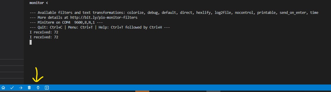
With the Arduino is plugged into the computer, open serial monitor in VSCode.
Note
If needed, visit https://docs.platformio.org/en/latest/projectconf/section_env_monitor.html to see how to change settings of serial monitor by editing platformio.ini
Try to send the message abc. You should see some text show up. That is the message sent by the Arduino!
You may notice that the TX and RX LED light up on the Arduino when you click "send". This is because TX and RX indicate serial communication.
The comments should be self-explanatory. Some further elaboration is given below:
Serial.begin(9600);means that we start the serial communication at 9600 bps baudrate. 9600 bps means that the serial communication speed is 9600 bits per second.Serial.read()reads one byte from the serial input stream.Serial.print()essentially writes a c-string to the serial output, which is actually a sequence ofchar(1 byte).
The meaning of I received 97 in the serial monitor is that 97 is the decimal form of
the character a in ASCII. In ASCII, every character is assigned a number from 0 to 127.

Section Check Box:
- Serial.read()
- Serial.write()
Digital input
We can get the input state by reading the voltage level of a pin. Some examples include light gate, limit switch, button. Google by yourself what these sensors look like!
Now, let's try to display the status of a push button in the serial monitor.
Breadboard
A breadboard is a simple device designed to let you create circuits without the need for soldering. They come in various sizes, and the design can vary, but as a general rule they look something like this:
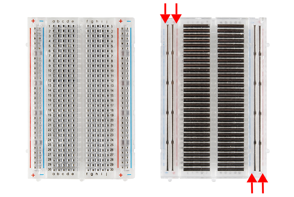
We can plug in wires and components into the holes of the breadboard easily. Once inserted that component will be electrically connected to anything else placed in that row. This is because the metal rows are conductive and allow current to flow from any point in that strip.
Connection
To implement this, you need a breadboard, a button, a resistor and several male-to-male Dupont wires prepared. Connect the components as bellows.
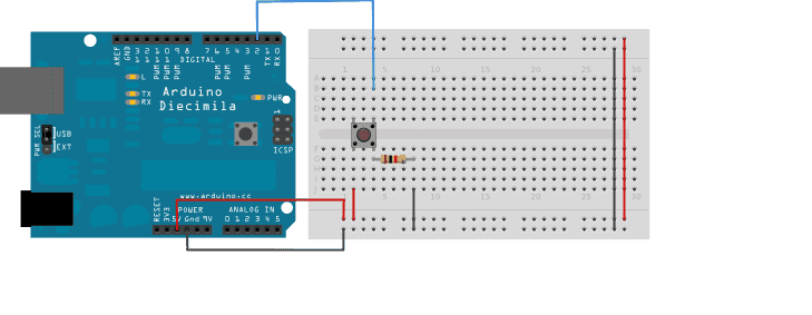
What is the purpose of the resistor?
When the input pin is neither pulled up or pulled down via a resistor, its reading is floating and we cannot determine its state, so always pull up / pull down the input pin before using it.
As mentioned before, apart from digitalWrite(pin, value) which controls the voltage output of the pin, we have digitalRead(pin) which reads the value from a specified digital pin. It will return either HIGH or LOW value, corresponding to 1 and 0.
The syntax digitalRead(pin) only takes 1 parameter, which is the digital pin you want to read.
Before you execute digitalRead(pin), you need to set the pin to INPUT mode first.
Upload the following code. The button reading will be displayed in the Serial monitor.
#define INPUT_PIN 2

void setup(){
    pinMode(INPUT_PIN, INPUT);
    Serial.begin(9600); // opens serial port, with 9600 baudrate
}

void loop() {
  int val = digitalRead(INPUT_PIN);  // read the input pin
  Serial.println(val);          // debug value
}
We can also use the internal pull up resistor instead
#define INPUT_PIN 2

void setup(){
    pinMode(INPUT_PIN, INPUT_PULLUP);
    Serial.begin(9600); // opens serial port, with 9600 baudrate
}

void loop() {
  int val = digitalRead(INPUT_PIN);  // read the input pin
  Serial.println(val);          // debug value
}
Classwork 1.2.1
Send a signal by button
Write an Arduino code which will light up LED 13 for 0.5 seconds when the button is pressed. The light turns off for 0.5 seconds afterwards, and then turn on again if the button is stilled pressed.
Please approach our team members after you have completed the task. In your training repository, save the code into a new file named cw-1-2-1.cpp. Commit and push the code. If you don't know how to use git/github, you can refer to the internal git tutorial here.
Section Check Box:
- What is a breadboard
- Using digitalRead()
The more you know
You can program the button such that a function is triggered based on the input value of the pin (e.g. trigger when the pin goes from low to high) via interrupt. It can be quite useful. See https://www.arduino.cc/reference/en/language/functions/external-interrupts/attachinterrupt/ for more information.
PWM output
You may notice that in the previous sections, the brightness of the LED on the Arduino is fixed. This is because the voltage provided by digitalWrite can only be HIGH or LOW, and we cannot set a "medium" brightness with it. To achieve "medium" brightness, we need to use PWM.
PWM is the abbreviation of Pulse Width Modulation.
There are 2 major functions:
- The length of the pulse width can be used to encoded data. Servo motor (which will be mentioned later) uses PWM to acquire the desire position.
- PWM wave can be used to control the power delivered to a desired value. In the example below, the brightness of an LED can be adjusted even though only 5V and 0V is delivered by the Arduino. Also, for a circuit with sufficient inductance, average analog waveform at the approximate desired voltage level can be recovered. L298N motor driver (which will be mentioned later) is an example.
In Arduino, PWM waves are generated with timers. The output pin is set to HIGH only when the conuter of the timer is lower then a preset value.
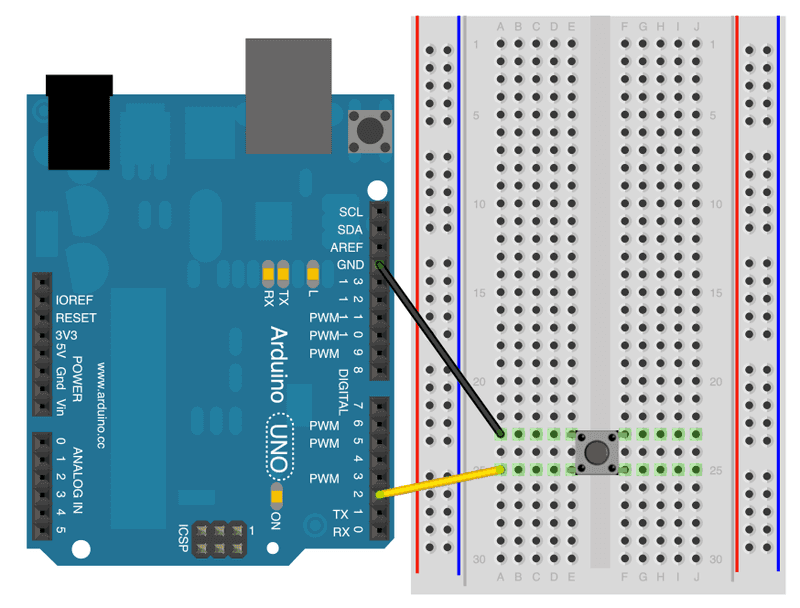
To use PWM control in Arduino, we need to use analogWrite(). Here we will use a LED to demostrate. Select one of the PWM pins. Connect the circuit as below (approach our team members if you don't understand this diagram!):
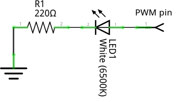
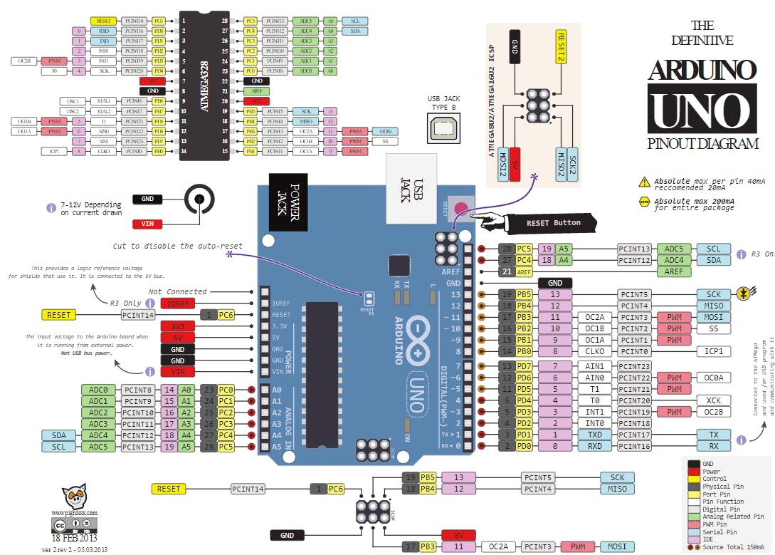
- Note that you cannot use the LED on the Arduino board (pin 13) to perform fade as that pin does not support PWM (see appendix for more).
- Therefore, you need to attach an LED to the board by yourself to a pin that supports PWM, e.g. pin 9.
- A pin supports PWM if it has the
~character printed next to it. (you may check the pinout for more information)
#define PWM_PIN ?

void setup(){
  pinMode(PWM_PIN, output);
  analogWrite(duty_cycle);
}

void loop() {

}
Change the value of PWM_PIN to the pin you've connected the LED, and try to change to value of duty_cycle you should see the brightness of the LED changes.
Classwork 1.2.2
Write a program such that the brightness of the LED
is changed (using analogWrite()) based on the serial input that is received.
- The user should be able to type a number from 0 to 255 in the terminal representing the duty cycle. The brightness of the LED should then be changed accordingly.
- After the brightness is changed, the Arduino should send a response message
Updated to %d(where%dis replaced by the brightness) via serial. - Perform serial I/O via the Serial Monitor.
- Hint: You need to use a function that translates c-string to integer (and perhaps vice-versa).
Please approach our team members after you have completed the task. In your training repository, save the code into a new file named cw-1-2-2.cpp. Commit and push the code. If you don't know how to use git/github, you can refer to the internal git tutorial here.
Section Check Box:
- What is PWM
- Using analogWrite()