Basic IO
One of the reason why we are using MCU like ATMega328p on Arduino or STM32 on our PCB to control electronic components is that typical computer doesn't provide GPIO for us to interface with other components, so it is important to learn how to manipulate IO pin on MCU.
Digital output
Upload the following program and connect an LED with a current limiting resistor to see how to Arduino toggles its pin.
#define OUTPUT_PIN
void setup() {
  pinMode(OUTPUT_PIN, OUTPUT);    // sets the digital pin 13 as output
}

void loop() {
  digitalWrite(OUTPUT_PIN, HIGH); // sets the digital pin 13 on
  delay(1000);            // waits for a second
  digitalWrite(OUTPUT_PIN, LOW);  // sets the digital pin 13 off
  delay(1000);            // waits for a second
}
Digital input
We can get the state of a light gate, limit switch, button... by reading the voltage level of the output pin.
Remember:
When the input pin is neither pulled up or pulled down, its reading is floating and we cannot determine its state, so always pull up / pull down the input pin before using it.
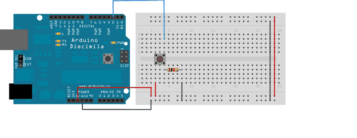
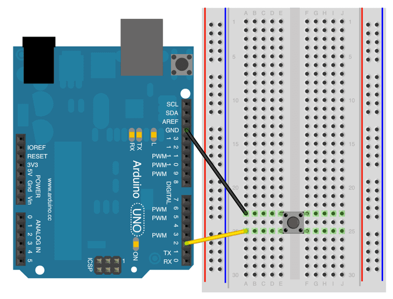
Connect a push button with a pull down resistor in this way, the reading will be sent out.
#define INPUT_PIN x
void setup(){
    pinMode(INPUT_PIN, INPUT);

}

void loop() {
  val = digitalRead(INPUT_PIN);  // read the input pin
  Serial.println(val);          // debug value
}
We can also use the internal pull up resistor instead
#define INPUT_PIN x
void setup(){
    pinMode(INPUT_PIN, INPUT_PULLUP);

}

void loop() {
  val = digitalRead(INPUT_PIN);  // read the input pin
  Serial.println(val);          // debug value
}
PWM output
PWM is the abbreviation of Pulse Width Modulation.
There are 2 major functions:
- The length of the pulse width can be used to encoded data. Servo motor (which will be mentioned later) uses PWM to acquire the desire position.
- PWM wave can be used to control the power delivered to a desired value. In the example below, the brightness of an LED can be adjusted even though only 5V and 0V is delivered by the Arduino. Also, for a circuit with sufficient inductance, average analog waveform at the approximate desired voltage level can be recovered. L298N motor driver (which will be mentioned later) is an example.
In Arduino, PWM waves are generated with timers. The output pin is set to HIGH only when the conuter of the timer is lower then a preset value.
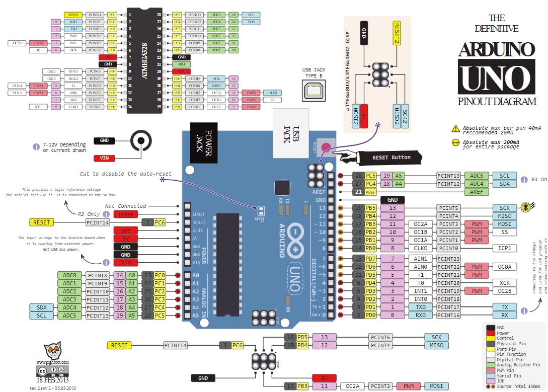
To use PWM control in Arduino, we need to use analogWrite(). Here we will use a LED to demostrate. Select one of the PWM pins (you may check the pinout). Connect the circuit as below:
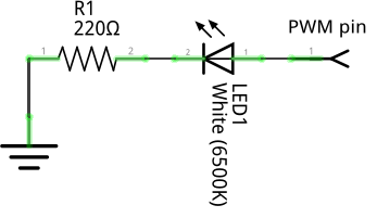
#define PWM_PIN ?
void setup(){
    pinMode(PWM_PIN, output);
    analogWrite(duty_cycle);
}
Change the value of PWM_PIN to the pin you've connected the LED, and try to change to value of duty_cycle you should see the brightness of the LED changes.
Section Check Box:
- What is PWM
- Using analogWrite()
Further Reading
ADC input
Some sensor gives reading by setting its output pin to a certain voltage, we can read its output using ADC module on Arduino and print it out using analogRead().
#define ADC_PIN x
void setup(){
    pinMode(ADC_PIN, INPUT);

}

void loop() {
  val = analogRead(ADC_PIN);  // read the input pin
  Serial.println(val);          // debug value
}
Further Reading